


CRISS CP/M technical reference
This document contains technical data that is required to use and understand CRISS CP/M computer.
Overview
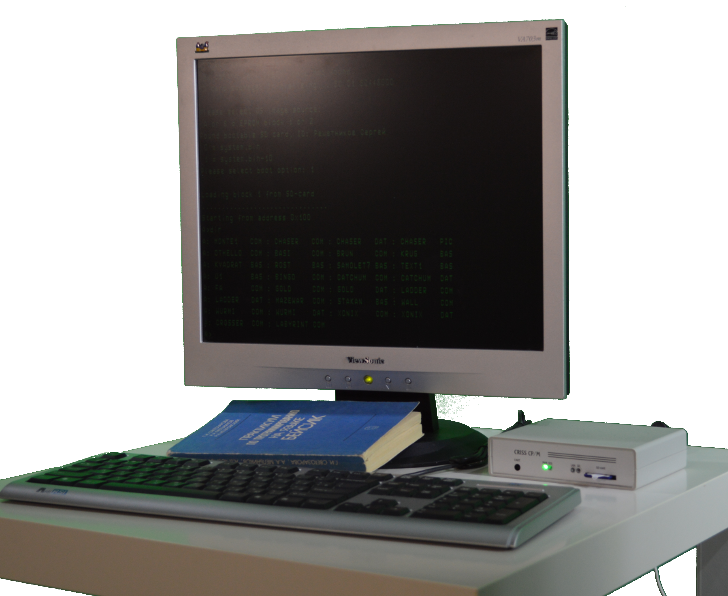
CRISS CP/M is a single-board personal computer.
Basic features:
- Power supply requirements: 120-230 AC
- Maximal consumption: 10 W
- Operational conditions: standard dry office/home environment
- Temperature range: form +5 to +40 C
- Water protection: No
Please take into account that it is not industrial of automotive device, do not expect too much from it! But in the standard home conditions it is very reliable.
PCB size is 100x130 mm, size in the enclosure (excluding power cord) is 140x110x35 mm, weight depending on the version could be 350-400 g.
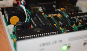
PCB structure
All components except power switch are located on the single double-sided PCB 130x100 mm, mounting holes are optimized for the GIANTA G738 enclosure.
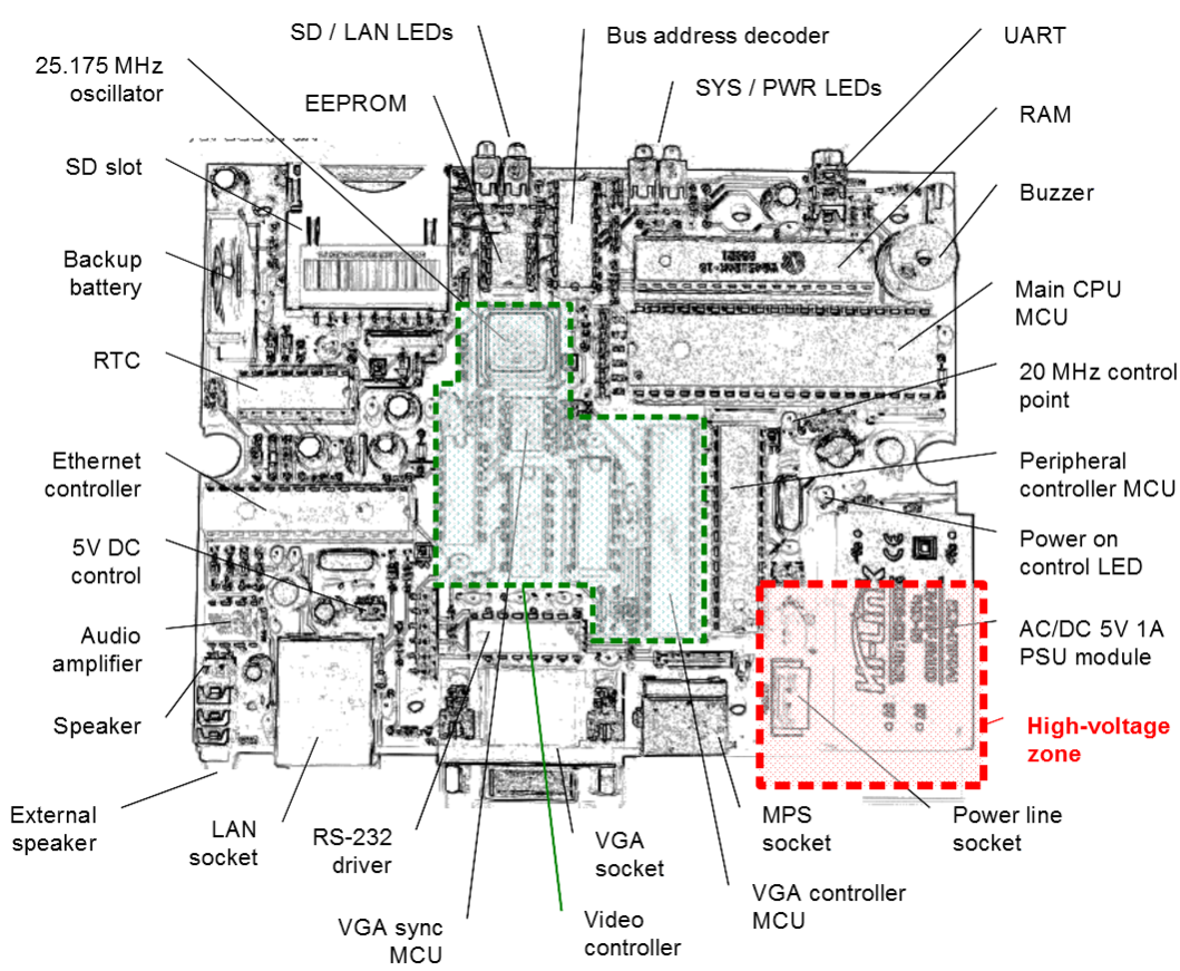
Important! The PCB has direct connection to the high-voltage power line. For the maintenance procedure alternative external 5V 1A power supply connected to the 5V DC control socket must be used!
Sockets
This section contains description and pinouts for the CRISS CP/M external sockets.
MPS Mini DIN 8 Female and Mini DIN 6 Female connectors:
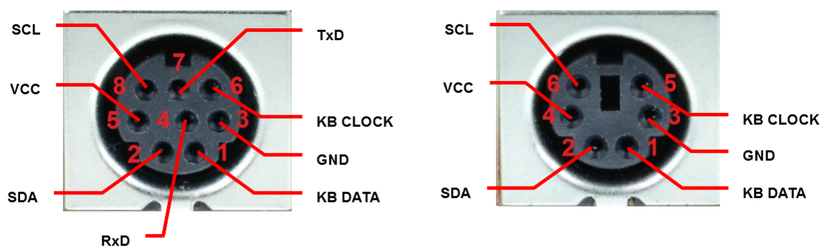
Pins description:
- GND - ground
- VCC - power supply for the external devices 4.8V 150mA max
- TxD, RxD - RS-232 interface
- KB CLOCK, KB DATA - PS/2 keyboard connection
- SCL, SDA - multipurpose lines that are used for GPIO, mouse connection etc.
External cables
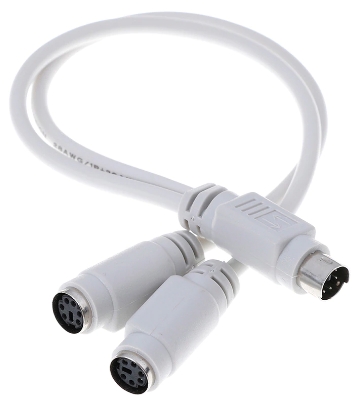
Standard version has by default MD6F din socket on the back panel and doesn't need any adapter to connect the keyboard. If you're going to use mouse or GPIO modules (LPT adapter in their order) you'll nedd to purchase or build so-called PS/2 Y Mouse and Keyboard Connector (Splitter). Its pinout can be found here: https://pinouts.ru/InputCables/ps2y_adapter_pinout.shtml. Please refer to the image how it looks like.
In the MAX version, due to the lack of space on the back panel, all interfaces are brought out but one communication socket, designated as MPS. Standard version also may be equipped with MD8F socket if you want to use RS-232 interface (serial printer, for example).
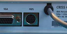
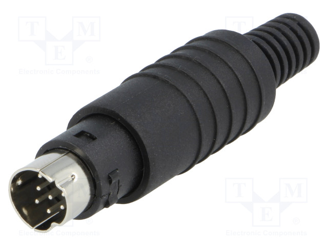
The MPS socket uses a Mini Din 8pin Male cable connector. To connect external devices, a splitter is required for which we recommend using a 4-wire cable from USB devices, the length of the splitter cable between the connectors should be approx. 20 cm.
The interfaces that are terminated on the MPS connector:
- PS/2 keyboard
- RS-232 interface for the connection of a printer or other peripherals
- I2C bus for GPIO block
- I2C bus for LPT interface
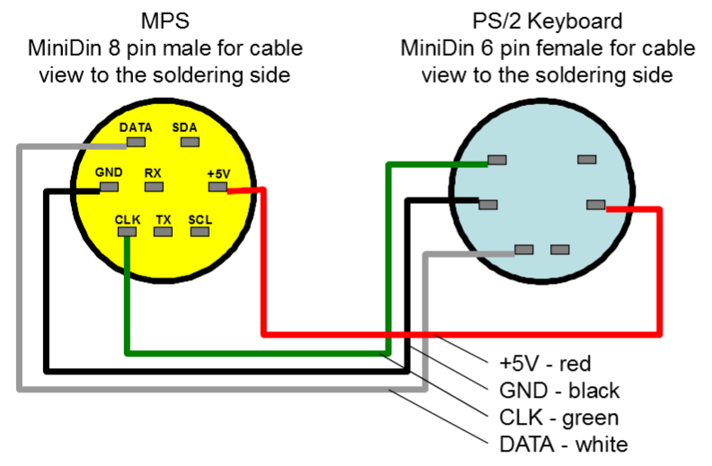
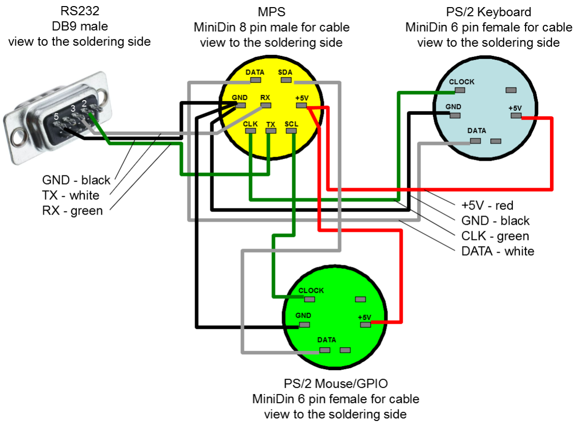
In the simplest case, the MAKS version requires an external connector to be made for connecting a keyboard. The wiring diagram and recommended conductor colours are shown in the illustration. Mounting side view.
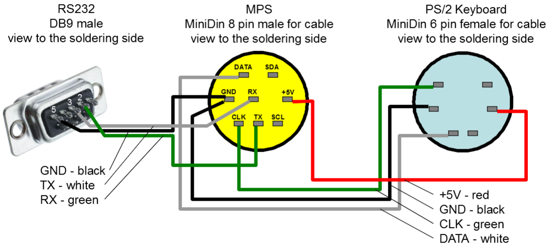
When a printer or other external device with RS-232 interface needs to be connected, the splitter includes a DB9 male connector:
To have mouse and LPT support and have standardized GPIO connector you need more complicated cable:
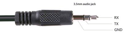
System UART cable has 3.5mm audio jack plug, it must be connected to the adapter as follow. Please note that pinout is not compatible with standard USB-3.5mm jack cable (really sorry for that), but if you want to make your CRISS compatible please just cross resistors R3 and R4 while assembling.
Firmware uploading and MCU re-programming
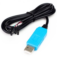
To install the updates you need a USB to UART adapter and a Windows PC to run the software that installs the updates. The adapter must support a transfer rate of at least 57600 baud. When connected, a new COM port will appear in the system, check the port number in the OS Device Manager. If necessary, install the drivers provided with the adapter.
To install the updates, proceed as follows
- switch off the power of the computer;
- open the case by removing the two fixing screws from the bottom of the case;
- very carefully remove the top cover to avoid damaging the cable to speaker attached to the top of the case;
- connect the adapter to the internal system programming connector, observing the order of connection (from left to right pins Rx, Tx, GND of the adapter), usually white - green - black, the red wire of the adapter must be securely isolated;
- run the bat-file of the installation package with the number of the COM-port as a parameter - the program will start and go into standby mode;
- turn on your computer - boot-up will start automatically accompanied by SYS indicator flashes and audible signals;
- when the installation is complete, power off the computer, disconnect the adapter, place the top cover and fasten it with the mounting screws.
Adding custom SPI module
One channel on the SPI bus is reserved for the user device, on the board there full set of pin connectors to attach to the SPI bus: CS, MISO, MOSI, SCK, GND, VCC. This module may be mounted as a "second-floor" PCB, body height allows that or its PCB may be located on the place of AC/DC module, in this case CRISS CP/M must be feed from the external 5V 1.5A DC PSU.
Firmware has several tools to support custom user devices:
- direct access to SPI bus to access from the CP/M programs;
- special I/O port that invokes user exit and calls custom user AVR program for better performance.
Please write requests if you need this feature - it will be described in more details.